

Cross Country Wireless VLF/LF/HF Antenna Amplifier
The VLF/LF/HF Antenna Amplifier contains all the electronics needed for home DIY construction of an extremely low noise active receiving antenna sensitive enough for remote rural use such as the Australian outback.
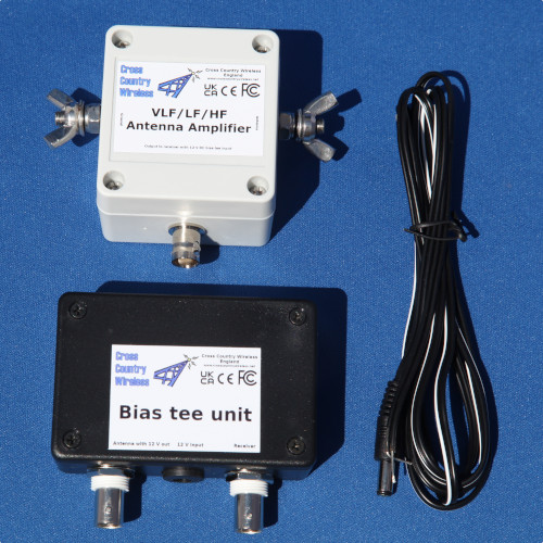
The amplifier consists of two units, a weatherproofed outdoor head unit for connection to a suitable ground mounted vertical wire or tube antenna of 3 to 5 m (9 to 15 feet) high and a ground rod and a bias tee unit to provide DC power up the coaxial cable to the outdoor unit.
The outdoor unit is housed in a polycarbonate box with stainless steel antenna connections and a BNC socket. The bias tee unit is a PCB with two BNC connectors and a DC socket to take DC power from a battery or power supply.
Like our other active antenna products it has RF overload protection to allow it to be used very close to transmit antennas without damaging the amplifier or the attached receiver.
The design of this amplifier is based on our original VLF/LF/HF Active Vertical Antenna and is an effective replacement for that antenna. This amplifier uses a JFET cascode design to reduce Miller effect to reduce capacitive loading of the antenna element for extra sensitivity at VLF frequencies. As usual with our antenna amplifiers a common mode choke filter is built in to the head unit to reduce noise on the feeder reaching the antenna.
This amplifier covers a wider frequency range and is more sensitive than our High Z Antenna Amplifier. However due to component tolerates we do not recommend using two or more VLF/LF/HF Antenna Amplifiers in a phased array. The High Z Antenna Amplifier was designed for multiple use in HF phased arrays.
For electrical safety with PME mains earthing systems a 1 A quick blow fuse is installed in the connection from the amplifier to the antenna ground terminal. This will blow and isolate the antenna ground in the rare case of a mains earth fault directing high fault current through the antenna ground. This will protect the coaxial cable feeder and all equipment connected to it from damage due to a mains earth fault. The antenna bleed resistor and 20 kA gas discharge tube antenna protection is connected directly between the antenna and ground terminals and is unaffected by the fuse.
Specifications:
Frequency range (VLF/LF/HF Antenna Amplifier): 5 kHz to 35 MHz
Input impedance: 1 M ohms
Output impedance: 50 ohms
OIP2: >+70 dBm
OIP3: >+32.5 dBm
Gain (head and base units VLF/LF/HF Antenna Amplifier): 15 dB at 14 MHz
Noise figure: 0.5 dB
Supply voltage (head unit): 10 to 20V DC from a bias-tee feed via the coaxial cable
Supply current (head unit fed with 13.8 V DC from bias-tee): 15 mA
VLF/LF/HF antenna outdoor unit connectors: Two M6 stainless steel threaded studs and BNC female (RF out 50 ohms)
Bias Tee Unit connections: BNC female (RF input and DC feed to outdoor unit), BNC female (RF output to receiver), DC connector (for 10 to 20 V DC power input)
For our professional and commercial customers we now have a Wise.com account so we can accept bank transfers in local currencies worldwide.
Contact us for a quotation.
Contact Chris Moulding via info@crosscountrywireless.net