

Cross Country Wireless Experimenter's Antenna Amplifier ++
The Experimenters Antenna Amplifier is ideal for Field Day, portable or temporary receiver installations where temporary antennas have to be rigged to take advantage of the space available. The RF overload protection allows it to be used very close to transmit antennas. It is also ideal for fixed installations.
It contains all the electronics needed for home DIY construction of a range of active antennas including small loops, Beverage, Flag and e-field probe types.
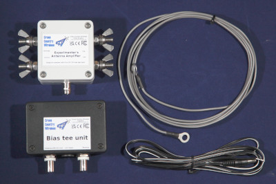
The amplifier consists of two units, a weatherproofed outdoor head unit for connection to a suitable loop and a bias tee unit to provide DC power up the coaxial cable to the outdoor unit.
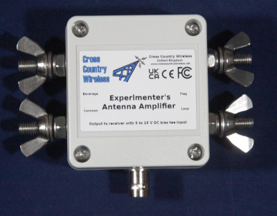
The outdoor unit is housed in a polycarbonate box with stainless steel antenna connections and a BNC socket. The bias tee unit is a PCB with two BNC connectors and a DC socket to take DC power from a battery or power supply with centre pin positive.
Like our other active antenna products it has RF overload protection to allow it to be used very close to transmit antennas without damaging the amplifier or the attached receiver.
The amplifier uses a tapped isolation transformer so that a range of antenna impedances can be used. We supply a 2.5 m (8 ft) length of wire as a simple loop to make a first loop for testing.
To isolate the antenna element from the receiver the amplifier has two isolation transformers in the input and a common mode choke on the 50 ohm output
Specifications:
Frequency range (Experimenter's Antenna Amplifier): 500 kHz to 55 MHz
Input impedance: Loop 50 ohms, Beverage 450 ohms, Flag 900 ohms
Output impedance: 50 ohms
OIP2: >+70 dBm
OIP3: >+32.5 dBm

Gain (head and base units Experimenters Antenna Amplifier): 25 dB at 14 MHz
Noise figure: 0.79 dB
Supply voltage (head unit): 9 to 15V from a bias-tee feed via the coaxial cable
Supply current (head unit fed with 13.8 V from bias-tee): 27 mA
Experimenter's antenna outdoor unit connectors: Four M6 stainless steel threaded studs (Common, Loop, Beverage and Flag) and BNC female (RF out 50 ohms)
Experimenter's antenna amplifier bias tee board connections: BNC female (RF input and DC feed to outdoor unit), BNC female (RF output to receiver), DC connector (for 9 to 15 V DC power input) centre pin positive
We use eBay for our individual customers as they look after the import tax and fees involved in international transactions.
The eBay listing is here.
If the eBay listing is sold out we have a regular stock situation post on the Cross Country Wireless Groups.IO forum..
We also announce new batches of our products on the Groups.IO forum.
For our professional and commercial customers we now have a Wise.com account so we can accept bank transfers in local currencies worldwide.
Contact us for a quotation.
Here are links to various antennas that can be built with the Experimenter's Antenna Amplifier:
Beverage's paper for the A.I.E.E in 1922. The 56 page report that covers the Beverage antenna development in full
Beverage's 9 page article for QST.
Beverage's 1921 original patent for the Wave antenna
Beverage's 1923 patent covering additional Wave antenna developments
Link to the KK5JY page on the Loop on Ground antenna
Many radio amateurs think that the Flag antenna was originally designed in the 1980s.
The original design was patented by Harold.H.Beverage of RCA back in 1941 with the original patent application made in 1938.
Yes, it's the same man who designed the Beverage Wave antenna back in 1921.
Click here for a copy of Harold Beverage's patent.
Earl Cunningham, K6SE independently developed the Flag antenna through antenna modelling various antennas in the 1990s. He was probably unaware of Beverage's previous work.
Here is a link to an excellent article on Flag, Pennant and Ewe antennas by W8JI
As the Flag and Pennant antennas designed by K6SE were intended for the 160 and 80m amateur bands Neil Kazaross developed the Kaz antenna for medium wave DXing.
Here is a link to an article on Kaz and SuperKaz antennas by John Bryant
One version of the Flag antenna modelled by Earl Cunningham, K6SE was later built by W2PM and called the Mini-Flag.
This used a diamond loop of wire with sides of 5 feet or 1.5 m. The feed point was at one corner with a 680 ohm resistor at the opposite feed point.
We used a version of this during the testing of the Flag Antenna Amplifier.
As the antenna is small in size the received signal level is low and it is a good test of the amplifier and it's internal common mode choke.
We expect to have a video demonstrating the amplifier with this antenna soon.
Contact Chris Moulding via info@crosscountrywireless.net