
HF Active Vee Antenna radiation pattern plots

HF Active Vee Antenna radiation pattern plots

Cross Country Wireless manufacture a HF Active Vee Antenna with a frequency range of 200 kHz to 70 MHz.
Recently we were asked by one of our customers to design an active antenna to replace some venerable Cold War era Rohde and Schwartz HF antennas used for HF radio monitoring. The original R&S antenna used an upright vee configuration that allowed ground wave vertically polarised, HF sky wave and NVIS signals to be monitored on one antenna. Our new active antenna uses the same configuration to give similar results in a smaller antenna.
Computer modeling and on-air testing shows that the antenna is elliptically polarised with a vertical component typically 6 dB below the horizontal one.
More details on the HF Active Vee Antenna can be found on the webpage.
All antenna plots are modeled with the antenna mounted 5m above poor ground i.e. with roads, paths etc as would be found in suburban or urban areas. The plots refer to radiation patterns but the antenna is a receive only antenna with a built in amplifier to compensate for reduced antenna gain at low frequencies.
The radiation pattern plots were prepared with the 4NEC2 antenna modeler and optimizer tool written by Arie Voors which can be downloaded here.
The NEC file of the CCW HF Vee Antenna can be downloaded here.
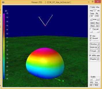
1 MHz total radiation pattern. Good for sky wave with some ground wave coverage.
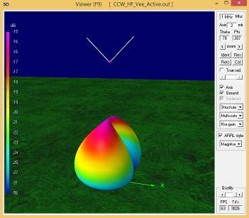
1 MHz horizontally polarised radiation pattern. Note the useful null that can be used to notch out interference from sky wave stations.
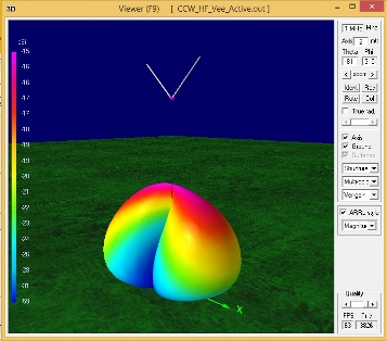
1 MHz vertically polarised radiation pattern. Note the useful null in the pattern that can be used to notch out local broadcast stations on ground wave.
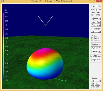
5.2 MHz total radiation pattern. Note that this pattern is ideal for NVIS reception on these frequencies.
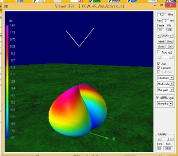
5.2 MHz horizontally polarised radiation pattern.
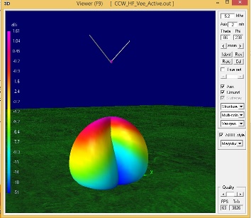
5.2 MHz vertically polarised radiation pattern.
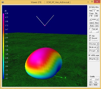
14 MHz total radiation pattern. The mounting height of 5m is too low for long distance work at this frequency. If the antenna was mounted at 10m or more above ground the main lobe of the radiation pattern would be closer to the horizon. Compare with the 28 MHz patterns.
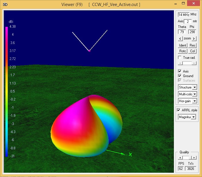
14 MHz horizontally polarised radiation pattern.
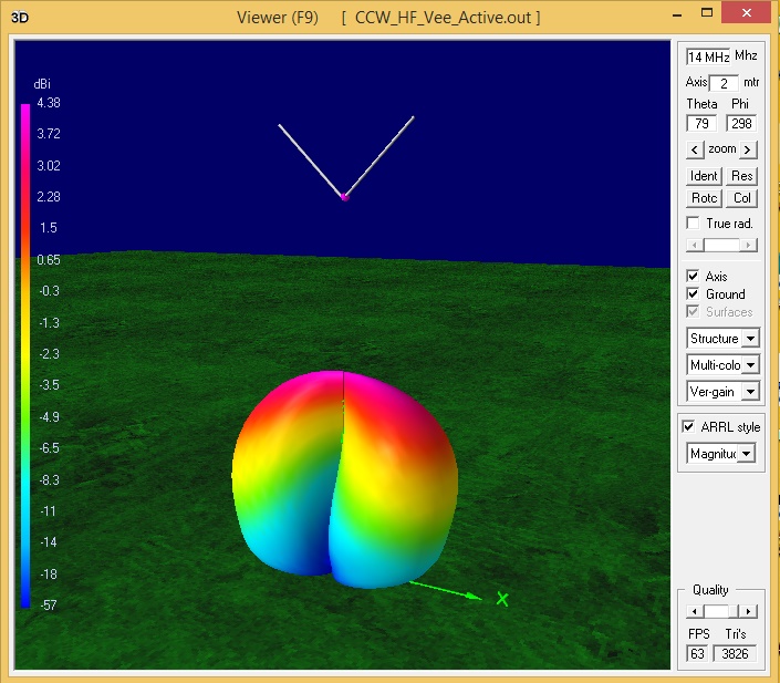
14 MHz vertically polarised radiation pattern
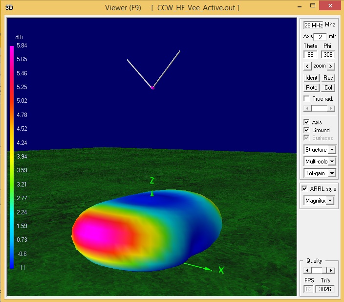
28 MHz total radiation pattern. The antenna is half a wavelength high at this frequency and the radiation pattern is closer to the horizon for long distance work.
28 MHz horizontally radiation pattern.
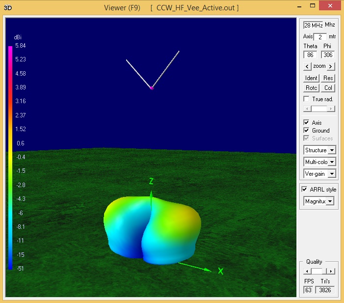
28 MHz vertically radiation pattern
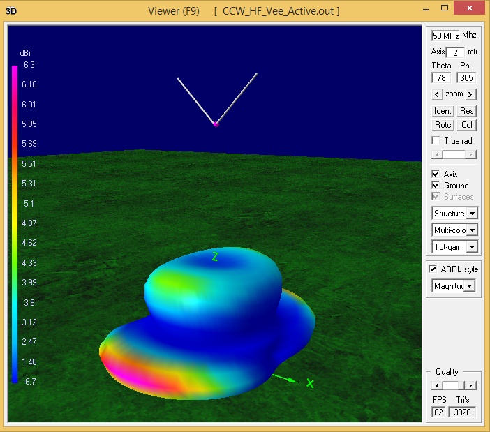
50 MHz total radiation pattern. The antenna is almost one wavelength high at this frequency and the radiation pattern is very close to the horizon for long distance work.

50 MHz horizontally polarised radiation pattern.

50 MHz vertically polarised radiation pattern
Contact Chris Moulding, G4HYG via info@crosscountrywireless.net for more details.